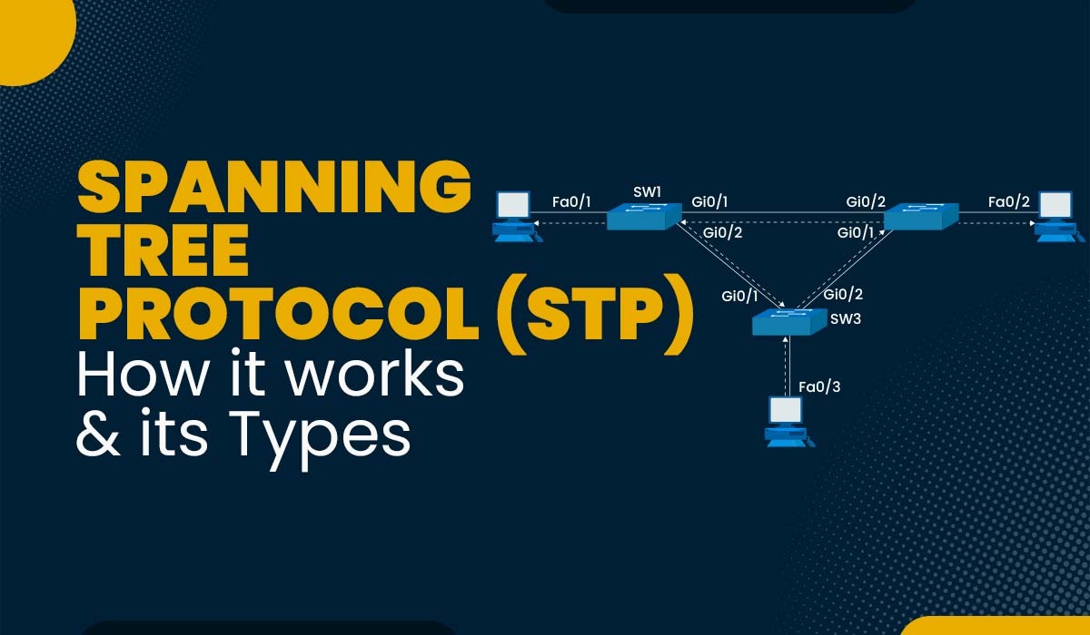
Spanning Tree Protocol (STP)
In the complex realm of computer networks, stability and efficiency are paramount. Imagine a scenario where multiple paths connect switches and bridges, forming a web of interconnected devices. While such redundancy promises increased reliability, it can also lead to unforeseen issues, like loops and broadcast storms, causing network outages and performance degradation. Therefore comes the Spanning Tree Protocol (STP), a fundamental mechanism designed to mitigate these problems and ensure seamless communication within networks. One of the protocols that a network engineer must grasp is spanning-tree, and if you decide to take the Cisco CCNA exam, you will undoubtedly come across it. In this article, you will learn the basics of spanning tree protocol, including how it works, its various types and states. So, let’s get started and understand what is Spanning Tree Protocol or STP. Spanning Tree Protocol (STP) is a Layer 2 network protocol; it is used to stop loops from forming inside a network topology. It was developed to prevent the issues that occur when computers exchange data over redundant channels in a Local Area Network (LAN). Data can become trapped in a loop that circles network segments if traffic flow is not carefully monitored and controlled. This can affect performance and bring traffic to a virtual standstill. If you have worked with network switches, you must have noticed that when we connect switches, there is some orange colour indication on the links, and then after 15-30 seconds, they turn to green colour. Any idea why this happens and what’s the reason behind this? The reason behind this mechanism is known as spanning tree protocol which avoids loops when you have multiple links between the switches. Let’s understand this by an example, we have three switches, and we’ll connect all these 3 switches. Then we will see the colour states change from orange to green because the ports go through some listening and learning stages, and all the switches do an election process. As you can see, the port states as well that they are going through listening and learning stages changes in colour as we have seen, but why is this all happening? Let’s deep dive into spanning tree protocol now! Whenever we have multiple links for redundancy or multiple switches which are connected together, STP occurs automatically on the network switches because it takes care of avoiding loops in the network, or we can say that if all the ports are in up or forwarding states, then there will lot of broadcast request generated inside your network. To avoid these kinds of scenarios in the network, Spanning tree protocol is there. How many loops are there in the network? When switches are linearly connected to each other, we have no chance of loops, but when multiple switches are connected, the loop can be there. Now, let’s see how the spanning tree protocol works. The working of STP is a 3-step process, which is – Spanning Tree Protocol works by selecting one of the switches as a head switch, considered as “Root Bridge.” So, what will happen as a result that now all of the frames in the network will only pass through the Root Bridge? And all redundant/backup paths will be put in a blocking state. So, there will be only one path reach from source to destination. – Hence, there will be no loop. Before understanding the working, let’s understand what exactly this term “Root Bridge” is. The root bridge is like the head in the L-2 topology and the most important switch, which has all ports in the forwarding state, which is selected by some election process. So, let’s try to understand the selection of root bridges. For the first time, when we connect multiple switches together, we see that in 30 seconds, the port states change from orange to green. In that case, there is an election process between all the switches. All the switches are exchanging BPDUs (Bridge Protocol Data Unit). In these BPDUs, all the connected switches exchange information like MAC Address, Priority number, port number, and all the necessary information to select the root bridge. When all the switches have exchanged their BPDUs with each other, the switch with the best (lowest) bridge-id is considered the root bridge. Bridge-id = Priority + MAC Address Note – Default priority value is 32768 on all switches Out of all the switches in the network, one is elected as a root bridge, and it becomes the focal point in the network; the rest all the remaining switches are known as non-root bridges. Let’s see with an example – We have connected three switches, and we’ll verify the Spanning Tree Protocol of all switches. As you can see from this image that when all three switches were exchanging the BPDUs with each other. All these are looking for the lowest bridge-id, a combination of “Priority + MAC.” But in our scenario, we have the same priority value on all the devices, so there is a tie-in priority. So, now MAC will be the second option per the bridge-id concept, so the least MAC Address we have is 0030.A3E3.B975 is now considered our root bridge. To verify – #show spanning-tree The nearest port to the root bridge is known as the root port. Every non-root bridge will have one root port. (Shortest path to reach on root bridge) because every non-root bridge will for the best path to reach the root bridge. We have some default STP port costs – Root Port – It’s always in the forwarding state and the best & shortest path to reach the root bridge. Designated Port – These ports are also in upstate; they always forward the data. Non-Designated Port – Ports that are in a blocking state. These are three processes explaining how Spanning Tree Protocol works. Now, let’s discuss the types of STP. There are 5 different types of STP listed below – Moving on, let’s see various STP Ports. There are five ports used in STP – These are the five ports in STP. Let’s understand Spanning tree port states now. There are five states through which a switch has to pass in STP. These are the 5 Spanning Tree Port States. Before STP modes, we understand the beginning of STP (Spanning Tree Protocol), which Radia Perlman introduced in 1985. After the protocol evolved in many ways and new changes were introduced, the Institute of Electrical and Electronics Engineers (IEEE) organized it. The following table shows an overview of the most frequently occurring Spanning Tree protocols, but these protocols do not support every bridge and switch. So, there are other spanning tree-inspired protocols that are not mentioned here. The original protocol standards are indicated in the IEEE Standards column, and the IEEE commonly rearranges these standards, making it difficult to track which standard currently includes STP functionality. For example, in the 802.1D-2004 revision, 802.1D was updated to include 802.1w. The 802.1Q standard was launched in 2014 with more functionality than that specified in 801.1D. The options used to specify the protocol mode when enabling STP on a bridge or switch are shown in the Switch column. To enable STP, a network manager connects to the device and then switches to global configuration mode and runs a command in the following format: spanning-tree mode <protocol mode> For example, Follow the below command to start Rapid STP (RSTP) on a switch spanning-tree mode rstp When STP is enabled, the manager must select a root bridge to act as the central STP reference point of the network, and the administrator also checks the root port and the specified port. (A root port is a bridge port that sends frames to the root bridge, whereas a specified port sends frames away from the root bridge). It determines how often switches send BPDUs. By default, BPDUs are sent every 2 seconds. It shows how long a port must spend in both a learning and listening state. (Listening to learning = 15 seconds) It shows how long a switch will retain BPDU information from a neighbour switch before discarding it. Transmission BPDU configurations, including their BIDs with a single switch, began to be considered root bridges. However, if a switch receives a BPDU with a high (low value) BID, then the switch configuration will hinder evolving BPDUs and will instead transfer these larger BPDUs to its neighbouring switches. When the root bridge is declared, a second election process is initiated to regulate the “root port” selection process. The process will follow the following steps until the root port is elected: STP, or Spanning Tree Protocol, is a network protocol that prevents loops in Ethernet networks. It designates a root bridge and calculates the shortest path to reach other switches, creating a loop-free topology. The main types of STP include Rapid Spanning Tree Protocol (RSTP), Multiple Spanning Tree Protocol (MSTP), Per VLAN spanning tree, Per VLAN spanning tree Plus, and STP (802.1D). VLAN (Virtual Local Area Network) is a logical segmentation of a network, while STP (Spanning Tree Protocol) is a network protocol that prevents loops in Ethernet networks. VLANs divide a network into separate broadcast domains, providing flexibility in managing network traffic, while STP ensures a loop-free topology by designating a root bridge and blocking redundant paths. Both technologies work together to enhance network performance and maintain stability. BPDU stands for Bridge Protocol Data Unit, which is a data message exchanged between network switches in Spanning Tree Protocol (STP) to communicate information about network topology and to prevent loops. The purpose of Spanning Tree Protocol (STP) is to prevent loops in Ethernet networks by creating a loop-free logical topology. It achieves this by designating a single switch as the root bridge and calculating the shortest path to reach other switches, while blocking redundant paths. STP ensures network stability, prevents broadcast storms, and enables efficient and reliable communication within the network. In this blog, we have discussed what is spanning tree protocol, how it works, what are its different types, etc. If you are still with us, you have already learned most things about STP. If you want advanced STP knowledge, you should join PyNet Labs’ CCNP ENCOR training. We hope you liked this article; please share your valuable feedback in the comment box below. Check out the “All Courses” Section to learn more about what PyNet Labs offers. You can also check out what our students say about us by clicking the “Student Review” section.Introduction
What is Spanning Tree Protocol (STP)?
 1")
 2")
 3")
 4")
How Spanning Tree Protocol (STP) Works?
 5")
STP Port Cost Link Type 100 Ethernet (10 Mbps) 19 Fast Ethernet (100 Mbps) 4 Gig Ethernet (1000 Mbps) 2 Gig Link (10 Gbps)
Types of Spanning Tree Protocol (STP)
Spanning Tree Protocol Ports
Spanning Tree Protocol Port States
What are STP Modes?
Protocol IEEE Standard Switch Description Spanning Tree Protocol (STP) IEEE 802.1D stp The Original STP Version Rapid STP (RSTP) IEE 802.1w rstp An evolution of STP 802.1D that addresses the STP Convergence time gap issue with enhanced BPDU exchange Multiple STP (MSTP) IEEE 802.1s mstp A format for mapping multiple VLANs into the same spanning tree to reduce processing on the switch Per-VLAN Spanning Tree (PVST+) Cisco Protocol based on 802.1D pvst An 802.1D enhancement that provides a separate STP instance for each VLAN configured in the network Rapid PVST+ Cisco Protocol based on 802.1w rapid-pvst An 802.1w enhancement that provides a separate STP instance for each VLAN, enabling faster convergence times Other terminologies associated with Spanning Tree Protocol
Port-Timer in STP
 6")
Hello Timer
Forward-Delay Timer
(Learning to forwarding = 15 seconds) Max Age Timer
STP Election Process
Frequently Asked Questions
Q1 – What is STP and its types?
Q2 – What is vlan and STP?
Q3 – What does BPDU stand for?
Q4 – What is the purpose of STP?
Conclusion