What is MSTP – Multiple Spanning Tree Protocol?
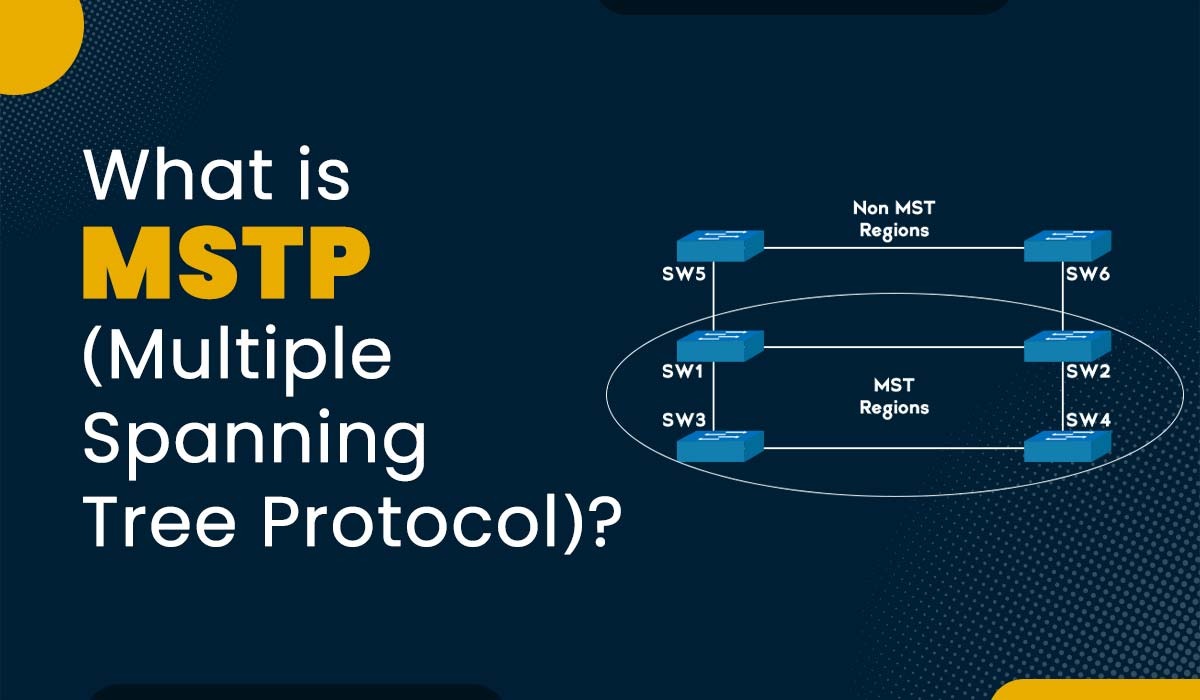
Networks are becoming more complex and demanding as the number of devices and applications increases. In order to ensure efficient communication, network engineers must utilize protocols that can handle Vlans, redundancy, and load balancing. One protocol that serves this purpose is MSTP. It is an extension of the STP (Spanning tree protocol), which assists in preventing loops and offers path redundancy in a network. With the help of MSTP, network engineers can create spanning trees with sets of VLANs and assign them to different switch ports. This way, it can optimize bandwidth use, reduce the convergence time, and simplify the configuration and management of the network. In this blog, we will explain what the MSTP protocol is, its purpose, implementation, advantages, and disadvantages. Let’s first understand what the MSTP protocol is. MSTP Protocol or Multiple Spanning Tree Protocol is defined in IEEE 802.1s standard. MSTP is based on RSTP, which means it inherits all the features and improvements of RSTP, such as fast convergence, port roles, port states, edge ports, link types, etc. But, apart from all the functionalities that are defined in RSTP, MSTP added some new ones, such as regions, instances, mapping, and digest. MSTP allows for creating multiple spanning trees within a single network. Each spanning tree is called an instance, and each instance can have its own root bridge and forwarding topology. Each instance can also be associated with one or more VLANs, which means that different VLANs can follow different paths on the same physical network. This can be useful for larger networks that require more flexibility and redundancy. The main purpose of MSTP is to optimize network performance and reliability by reducing the number of spanning tree instances and allowing different VLANs to follow different paths. MSTP also simplifies network configuration and management by using a common set of parameters for all instances within a region. There are various limitations to previous versions of protocols such as RSTP. When we talk about RSTP or Rapid Spanning Tree Protocol, it is an upgraded version of the original STP. RSTP was introduced in order to prevent loops in a single broadcast domain. Still, RSTP has limitations when it comes to networks with multiple VLANs. Some of these are: MSTP addresses all the above limitations. It introduces the concept of MST regions and MST instances. An MST region is a group of switches that run the MSTP protocol and have the same configuration parameters. An MST instance is a logical structure that defines a single forwarding topology for a set of VLANs within an MST region. Each MST instance has its own root bridge and priority values, as well as its own port roles and states. Now that we have a basic understanding of MSTP along with its different purposes. Let’s discuss the implementation of the multiple-spanning tree protocol. In order to implement the MSTP protocol on your network, we have provided some steps to follow. The first step is to define an MST region. An MST region is defined as the group of switches that run MSTP and have the same configuration parameters. These parameters include: Note: It is crucial to consistently configure these parameters on all regional switches. If not, the switches will not be able to exchange MST information and will fall back to RSTP mode. The second step is to configure an MST instance. An MST instance is a logical entity that defines a single spanning tree for a set of VLANs. One needs to configure these parameters for each instance: The third step is to configure an MST boundary. An MST boundary is a point where an MST region connects to another MST region or a non-MST network. One has to configure these parameters for each boundary: Let’s now understand the implementation of MSTP protocol with the help of a topology. In this topology there are four switches i.e., SW1, SW2, SW3, and SW4. We have four VLANs namely VLAN 10, VLAN 20, VLAN 30, and VLAN 40. We also assume that we create two instances of spanning trees i.e., Instance one for VLAN 10 and VLAN 20, and Instance 2 for VLAN 30 and VLAN 40. Below, we have provided the topology for better understanding. The first step is to define an MST region like we discussed above. In this case, we will define the MST region for SW1, SW2, and SW3. Let’s name it REGION1 and assign it a revision number of 1. Further, we map VLAN 10 and VLAN 20 to Instance 1, and VLAN 30 and VLAN 40 to Instance 2. We can use the commands as shown below on each switch. switch(config)#spanning-tree mode mst switch(config)#spanning-tree mst configuration switch(config-mst)#name REGION1 switch(config-mst)#revision 1 switch(config-mst)#instance 1 vlan 10,20 switch(config-mst)#instance 2 vlan 30,40 switch(config-mst)#exit Note: One must use the above command for each switch separately. Moving on to the next step i.e., configure the root bridge priority and port priority for each instance in the region. We will make SW1 the root bridge for Instance 1, and SW2 the root bridge for Instance 2. We will also lower the port priority of SW3’s ports connected to SW1 and SW2 so that they become designated ports. We can use the commands as discussed below on each switch: SW1(config)# spanning-tree mst 1 priority 0 SW1(config)# spanning-tree mst 2 priority 4096 SW2(config)# spanning-tree mst 1 priority 4096 SW2(config)# spanning-tree mst 2 priority 0 SW3(config)# interface <interface_connected_to_SW1> SW3(config-if)# spanning-tree mst 1 port-priority 128 SW3(config-if)# exit SW3(config)# interface <interface_connected_to_SW2> SW3(config-if)# spanning-tree mst 2 port-priority 128 SW3(config-if)# exit Let’s now understand the MSTP protocol frame in detail. MSTP makes use of BPDUs (Bridge Protocol Data Units) in order to exchange information between spanning tree-compatible devices. BPDUs can be explained as special frames that hold information such as bridge ID, root ID, port ID, etc. These are sent periodically or when there is a topology change. Below, we have explained all the fields in the BPDU. NOTE: The first 13 fields are the same as RSTP BPDU. The other six fields we have explained. Let’s now discuss the advantages and disadvantages of MSTP Protocol. Some of the advantages of multiple spanning tree protocol are: Apart from all the advantages we have just discussed, MSTP has some disadvantages. Some of these are: These are the advantages and disadvantages of MSTP Protocol. RSTP and MSTP are types of Spanning Tree Protocols mainly used to prevent network loops. The main difference between the RSTP and MSTP is that in the case of RSTP, it supports only one instance of a spanning tree. On the other hand, MSTP supports multiple instances for different VLANs. The primary purpose of MSTP is to allow multiple VLANs to share a single spanning tree instance. This result reduces the number of logical links and improves network efficiency. MSTP in telecom stands for multi-service transport platform. It is based on SDH (Synchronous Digital Hierarchy) and provides unified network management. MSTP and PVST are both spanning tree protocols. MSTP maps multiple VLANs to a single spanning tree instance, while PVST runs a separate spanning tree instance for each VLAN. In this blog, we have explained the MSTP or multiple spanning tree protocol. We have discussed the purpose of the MSTP protocol, its implementation, advantages, and disadvantages. We also have explained the different fields in the MSTP protocol frame. Still, if you have any doubts, feel free to use the comment section below.Introduction
What is the MSTP Protocol?
Purpose of Multiple Spanning Tree Protocol
How to Implement the MSTP Protocol?
Define MST region

Configuring MST instance

Configuring MST boundary

Multiple Spanning Tree Protocol Frame

Advantages of Multiple Spanning Tree Protocol
Disadvantages of Multiple Spanning Tree Protocol
Frequently Asked Questions
Q1. What is difference between RSTP and MSTP?
Q2. What is the primary purpose for MSTP?
Q3. What is MSTP in telecom?
Q4. What is the difference between MSTP and PVST?
Conclusion