OSPF States Explained
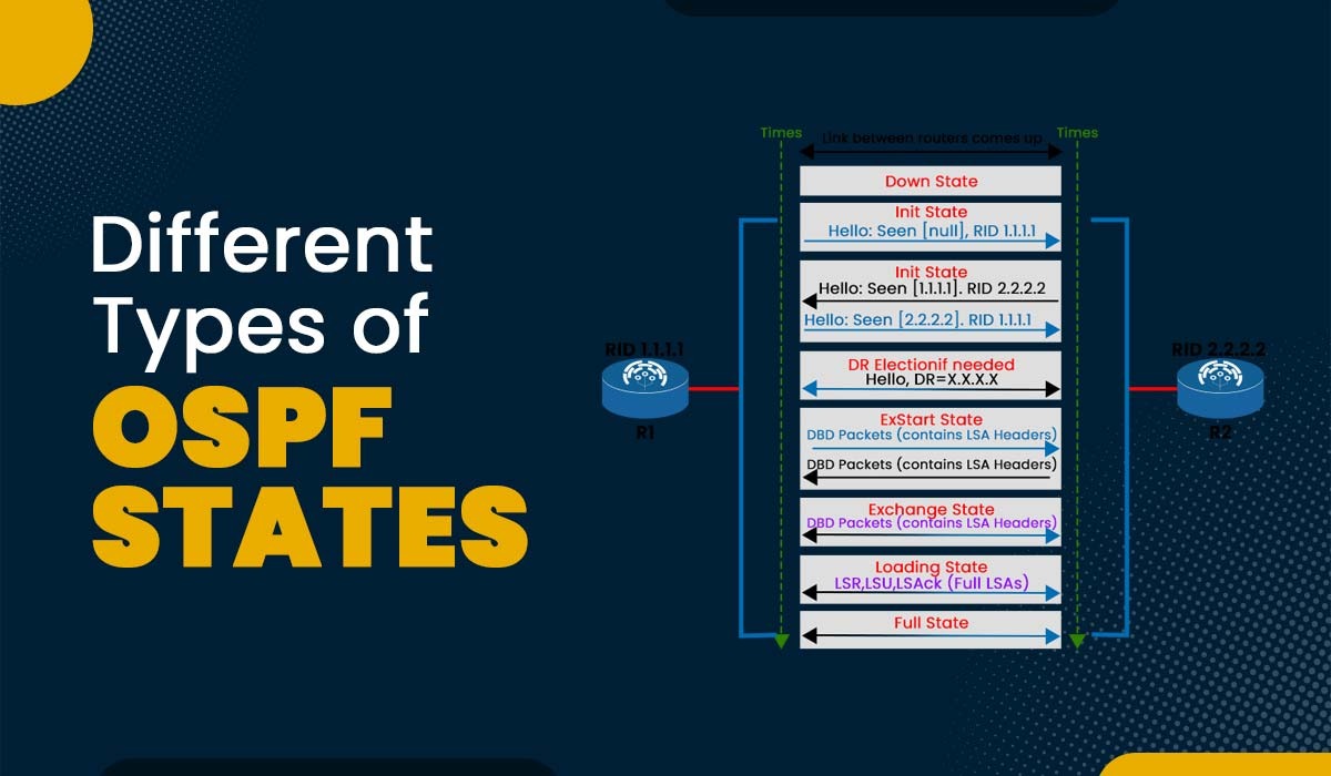
To achieve complete adjacency, OSPF routers undergo many states. In this blog, we will discuss the progression of OSPF states, from Down State to the Full State. Additionally, we will look at the requirements that must be met for OSPF to transition from one state to the next. It is important to note that it is essential that both interfaces on the router should be up and available through Layer 3 connectivity. Before getting into further details of OSPF neighbor states, let’s first understand what OSPF really is. OSPF stands for Open Shortest Path First and is a link-state routing protocol. This protocol makes it easy to find the shortest path between the source and destination router. It determines the best path by implementing the shortest path first algorithm. OSPF is one of the widely used IGPs for large networks. We already have discussed the basic definition of OSPF protocol; now, let’s discuss different OSPF neighbor states in detail. Before an OSPF-enabled router can become completely adjacent to its neighbors, it must go through a series of steps known as OSPF states. These OSPF neighbor states are very important for routers to communicate with each other and decide the best pathway to send data. OSPF routers establish connections with one another through eight states. These are: Let’s discuss these eight OSPF neighbor states in detail. Down State is known as the initial stage of neighbor in which no data (Hellos) have been received from the neighbor, but you can still send them hello packets. OSPF neighbor state changes from Full to Down occur under two conditions. Firstly, if an adjacent router fails to receive a hello packet from a neighboring router within the specified Router Dead Interval time, which is typically set to 4* the Hello Interval. Secondly, if a manually configured neighbor is removed from the configuration. Attempt state is the second stage in which the building of the neighborship process starts. It is only for manually configured neighbors on NBMA (Non-Broadcast Multi-Access) networks. One such example of NBMA networks is frame relay. At this stage, the router is attempting to connect with its neighbors via OSPF, but it hasn’t been successful so far. In the Init state, a router has knowledge of the existence of another router. However, it needs the necessary information to engage in the exchange of routing updates with that router. In simple words, when a router receives a hello packet from a neighbor, it must list the sender’s router ID in its next hello packet as an acknowledgment that it received a valid hello packet. But at this stage, only the hello packet is received from the neighbor, but 2-way communication has yet to be established. This state signifies that bi-directional communication has been established between two routers. Bi-directional means that each router has seen the other router’s hello packet and acknowledged it by listing its router ID in the neighbor list. At this state, a router decides whether to become adjacent to the neighbor or not. On broadcast networks (such as Ethernet) and NBMA networks, a router becomes fully adjacent only with the designated router (DR) and the backup designated router (BDR); it stays in the 2-Way state with all other neighbors. On point-to-point networks (such as serial links) and point-to-multipoint networks (such as MPLS), a router becomes fully adjacent to every neighbor. Note: Both DR and BDR are elected on broadcast and NBMA networks to minimize the number of adjacencies and reduce the amount of link-state information exchanged. When we talk specifically about DR, it is responsible for distributing LSAs to all other routers on the network segment, whereas BDR acts as a backup in case DR fails. The Exstart state acts as the initial stage in the process of forming adjacencies. During this state, the local router and its neighboring router work together to determine which router will be responsible for synchronizing the database. At this stage, the router negotiates with the neighbor in order to exchange DBDs (Database Description packets). If we talk about DBDs, these are mainly used to describe the contents of link-state databases and also detect any missing or outdated LSAs. Also, the master-slave relationship is established at this stage. The master router is the one that starts the DBD exchange and assigns the sequence numbers to the DBDs. The slave router is the one that follows the master’s sequence numbers and acknowledges the received DBDs. Note: The router with the highest router ID becomes the master and the one with the lower router ID becomes a slave. This state is where the actual DBD exchange takes place. The routers send and receive DBDs that contain summaries of their LSAs. Each DBD has a sequence number that is incremented by one for each new packet. The routers must keep track of the sequence numbers and acknowledge each received DBD. Further, the router checks for updated or extra link-state information from its neighbor by comparing the contents of the Database Descriptor (DBD) it receives with the contents of its own Link State Database (LSD). After this, the state changes to loading. During the loading state, OSPF routers engage in the exchange of Link State Requests (LSR) and Link State Updates (LSU), which include all Link State Advertisements (LSA). The updates are derived from the DDP or Data Base Descriptors (DBD) of neighboring entities. Link State Updates (LSUs) are packets that encapsulate all of the Link State Advertisements (LSAs) that have been transmitted to OSPF neighbors, transmitting recent updates or newly discovered network information. The Loading state is complete when both routers have received all the requested LSAs from their neighbors. At this point, both routers have identical link-state databases and can calculate their shortest paths using the SPF algorithm. The state then changes to Full. The full state is the operational state of OSPF, indicating that the network is functioning as expected. The databases of all routers are in perfect sync, and periodic Link State Advertisements (LSAs) are sent and received by all routers in the network. It is noteworthy that in the case of Broadcast networks and NBMA media, routers will only achieve Full State with their designated router (DR) and backup designated router (BDR) routers. In the context of point-to-point and point-to-multipoint networks, a router must maintain its full state with respect to each neighboring router. These are the OSPF neighbor States that a network engineer must be familiar with. OSPF is a type of IGP that uses the SPF algorithm to determine the best route. There are 8 OSPF states. These are: Down, Attempt, Init, 2Way, Exstart, Exchange, Loading, and Full. The three OSPF states involved in establishing the neighboring router are Down, Init, and 2-Way. 5 types of OSPF areas are: Backbone area (area 0), Standard area, Stub area, Totally stubby area, and No so stubby area (NSSA). LSA stands for Link State Advertisement. It is a packet that contains information about the network topology and is exchanged between routers in OSPF. OSPF states are an important topic in understanding the working of OSPF. In this blog post, we have explained how OSPF establishes adjacencies with neighboring routers using different states. We have also explained how OSPF exchanges routing information using various types of packets.Introduction
What is OSPF?
Different Types of OSPF States
Down State
Attempt State
Init State
2-Way State
Exstart State
Exchange State
Loading State
Full State
Frequently Asked Questions
Q1 – What is OSPF and its states?
Q2 – What are the three OSPF states?
Q3 – What are the 5 types of OSPF area?
Q4 – What is LSA in OSPF?
Conclusion